Build Your Own Light Pipe
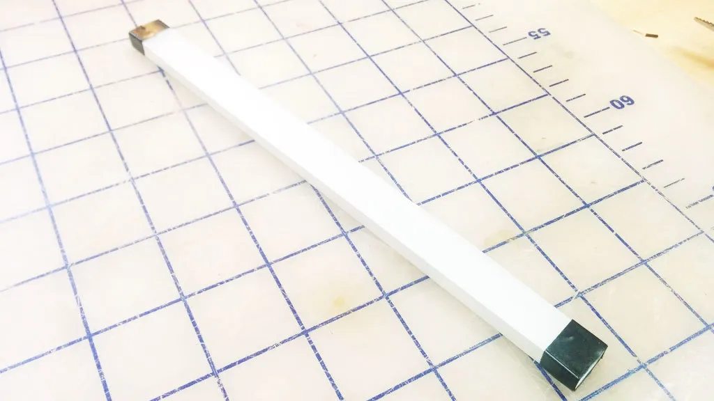
Light guides are physical tools that transmit light along a path from an illumination source while maintaining constant brightness. They’re often used in products to create a line of light that is consistently bright and dynamic-looking, even when it comes from a single source. Unfortunately, there is no simple how-to guide available for making them. The process is kept tightly guarded by optical engineering companies. We came up with a quick process to make our own light guides, and now you can too.
We built a light pipe, which, in principle, can be viewed as a fiber optic cable. All the sides are polished to a clear finish so that the light can be reflected internally inside the pipe. If the light hits a section of pipe where the surface is not perfectly reflective, like if it’s gouged or scratched, it will use that section as an "emitter" and attempt to escape the pipe. We take advantage of this by covering the bottom surface of the pipe with dimples. To make the path consistently bright, we arranged the dimples in a gradient with fewer dimples closer to the source, where the light from LEDs is brightest, and more dimples to catch the light farther along the light path (where the light is dimmest).
This step-by-step guide describes our process of quick experimentation and prototyping to achieve good illumination without having to run extensive light bouncing simulations. The design is created in Illustrator using blend modes, and the light pipe is manufactured with a laser cutter on 1/4" thick clear acrylic.
Please note that results will vary depending on many factors. The optical design, LED brightness, and beam angle are important factors to consider.

1. Open a new Illustrator document and draw a rectangle. We chose 8" x .5".

2. Make a guide and space it roughly 1/4" away from the edge of the rectangle. This is where the dimple pattern will begin. (Leaving a 1/4” margin allows us to later mask off the area to prevent seeing excessive LED brightness near the source in the light pipe.) Now draw a circle with a .005" diameter.

3. ALT + Click and drag the circle to duplicate it, and move it to the other side of the rectangle. The two circles mark the two ends of the dimple pattern.

4. Select both circles and create a blend.

5. Open up the blend options to fine-tune the blend.
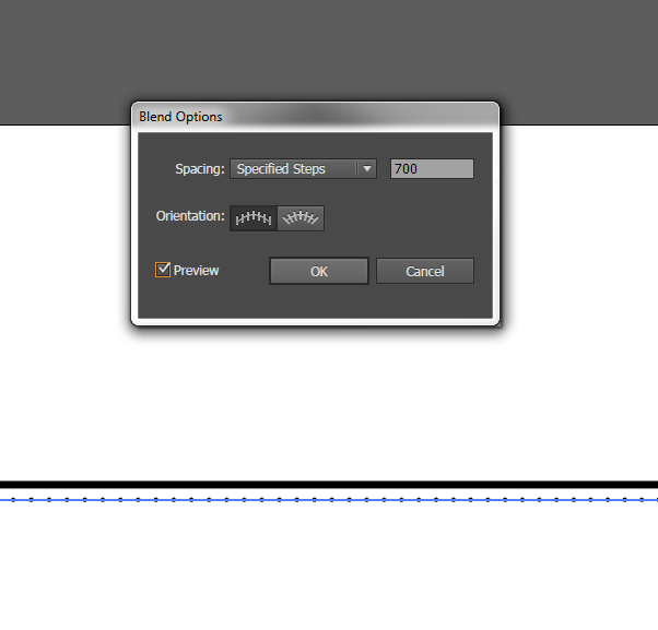
6. Change the spacing to "Specified Steps" and set the number to 700.
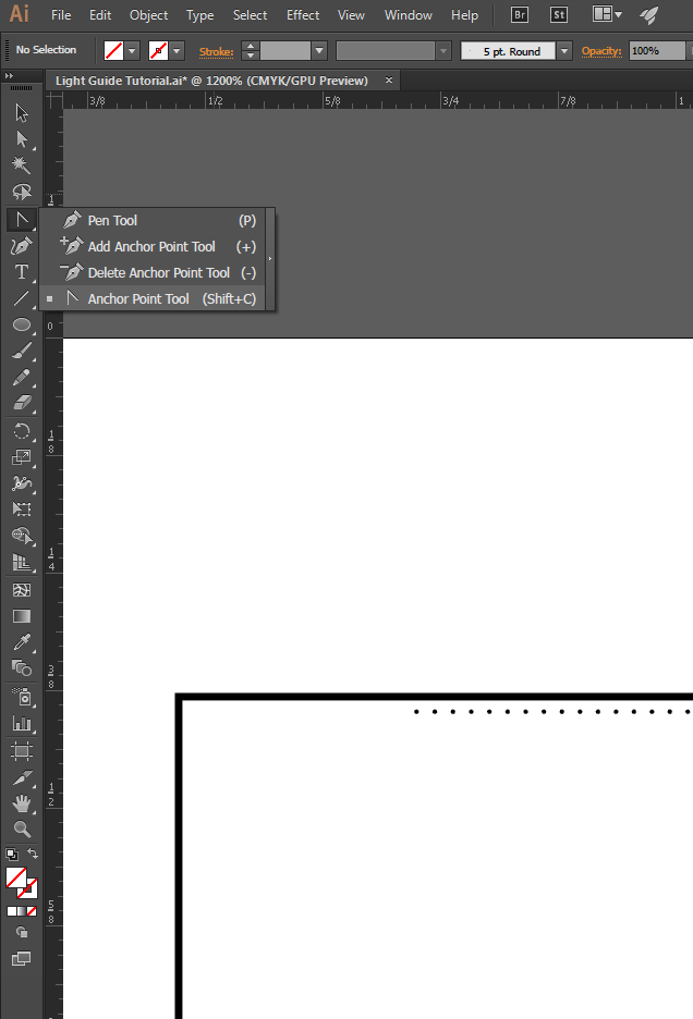
7. You should see 700 evenly spaced dots! In order to get them to start off sparsely spaced and then get closer together, we'll modify the path of the blend. Select the Anchor Point Tool (Shift + C).
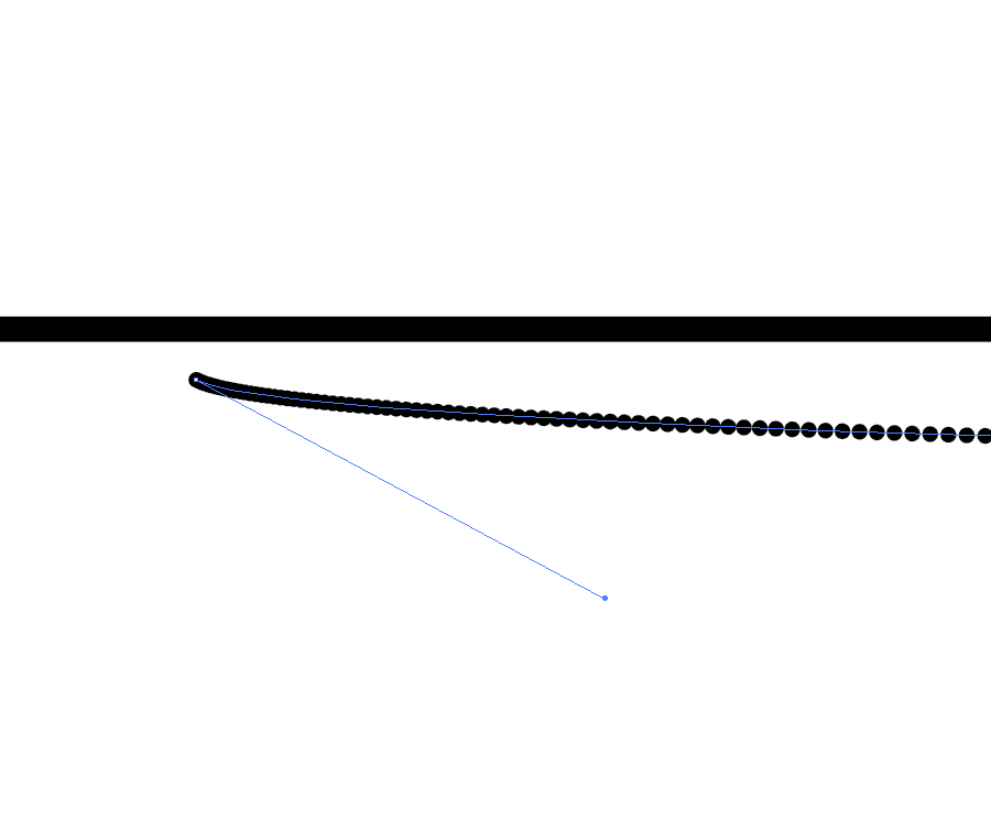
8. Use the white arrow to select the first point and drag it until you see the spacing start to change.
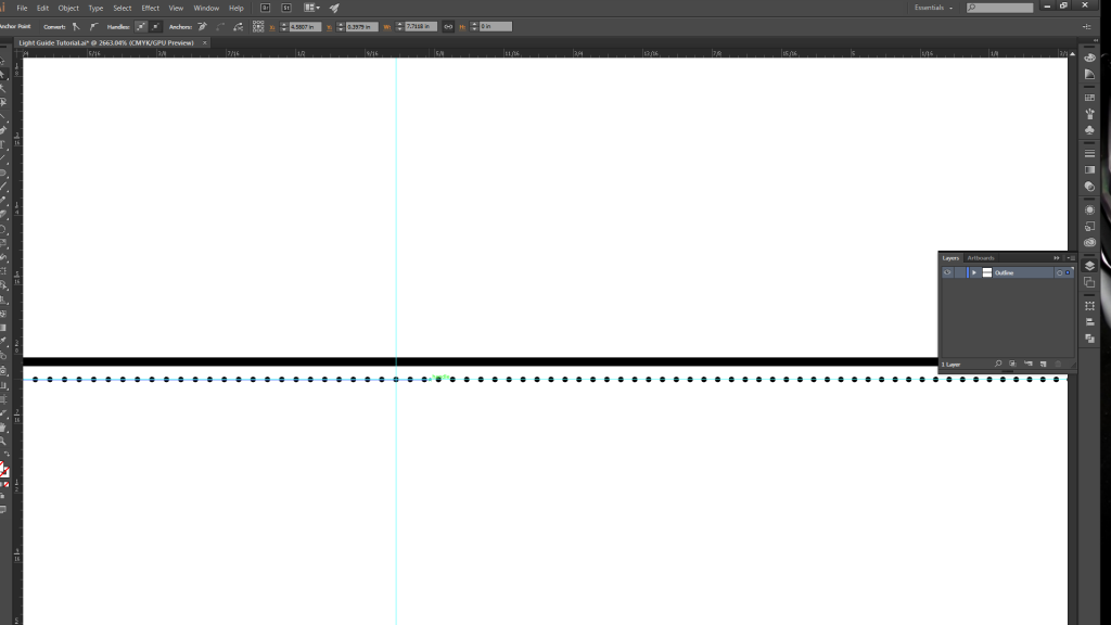
9. Create another guide halfway along the path, and then drag the anchor point (with the white arrow selection tool) just past the guide. Repeat the same process with the last circle, but move its anchor point about half an inch to the right.
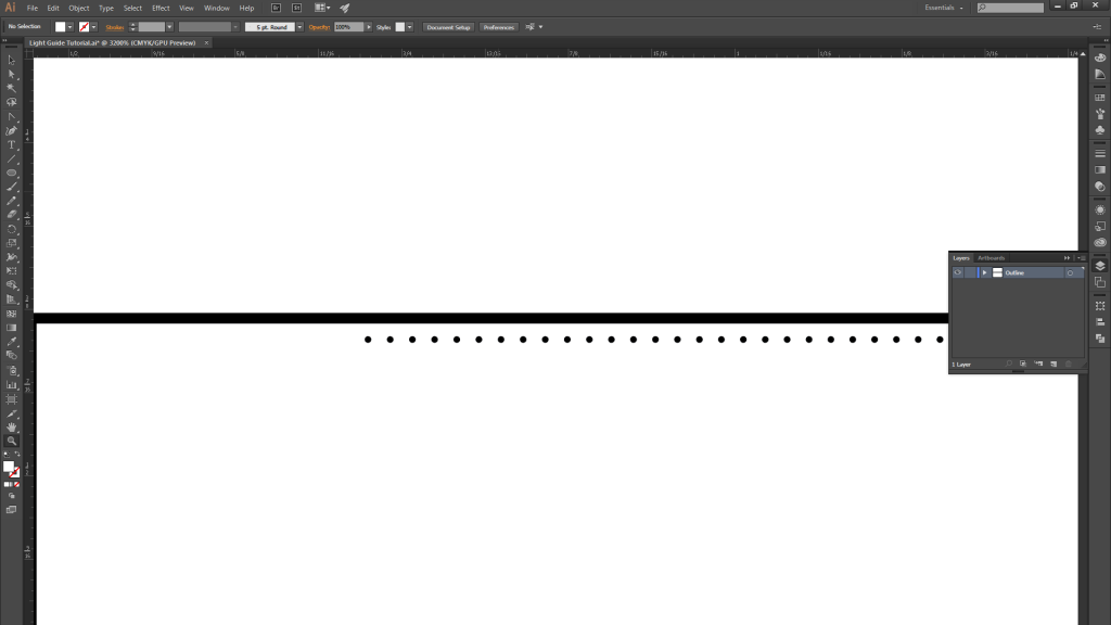
10. You should now have a gradient spacing of 700 circles becoming more closely spaced as you move from left…

11. …to right.
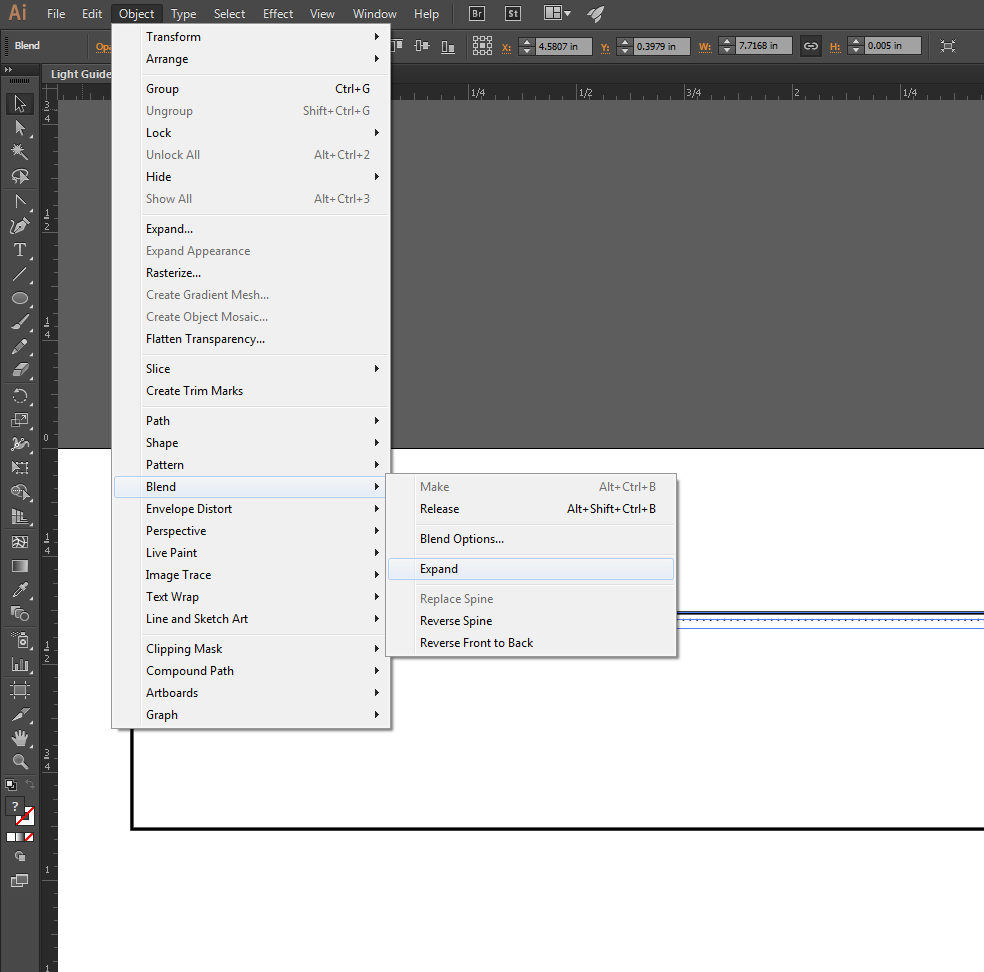
12. Once you are satisfied with the blend, expand it.
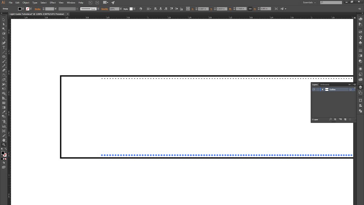
13. ALT+Click and drag the blend to copy it, and place it at the bottom of the rectangle.
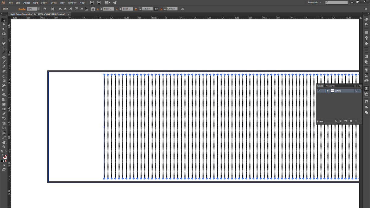
14. Select both blends and then use the instructions from Step 4 to create another blend.
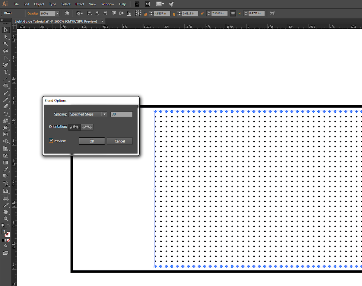
15. Use the instructions from Step 5 to fine-tune the new blend.

16. We chose to give our pattern a little bit of randomness, so we ALT+Click-ed and dragged the blend down and to the right ever so slightly.

17. With that, we’re ready for the laser cutter! This process is pretty quick to prototype (roughly 15 minutes from start to finish), so explore different gradient patterns and techniques, and try light pipes that are curved or bent (just keep in mind the critical angle).

18. Next, we raster the dot pattern on 1/4″ thick acrylic. Be sure the acrylic surface is clean and scratch-free.
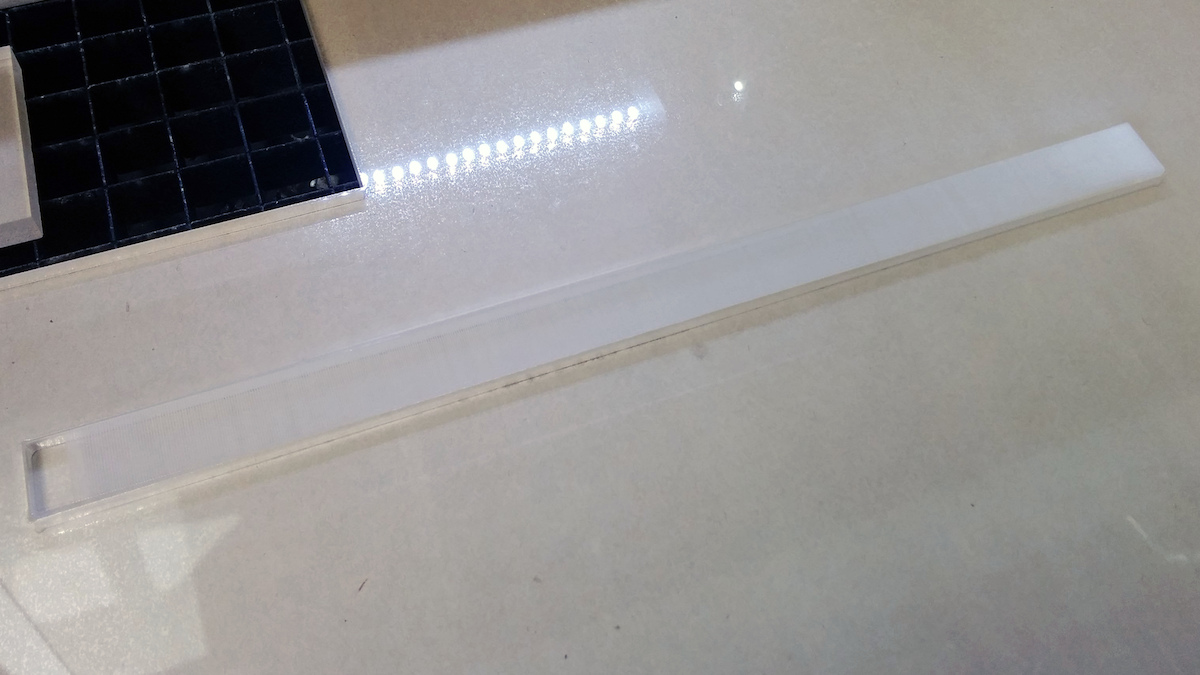
19. Different laser cutters have different settings for varying materials and thicknesses, so keep that in mind when choosing your settings. We used a speed of 80, power of 50 and maximum PPI for the raster. For the vector cuts, we took 4 cuts at speed of 4, power of 95, and maximum PPI.
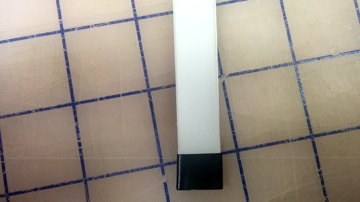
20. Now take your light guide and examine the edges. Make sure the material is transparent; otherwise you’ll need to do some hand-polishing.
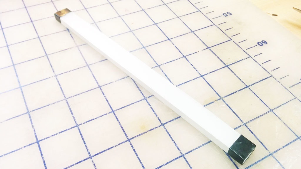
21. The slightly bumpy yet clear finish the laser leaves after a cut works great for our purposes. You’ll want to surround all clear surfaces with white reflective paper or tape, and mask off the quarter inch where the light first enters the pipe.

22. Here are the results with a super-bright LED! You can see that the light starts to drop off a little toward the end of the pipe.
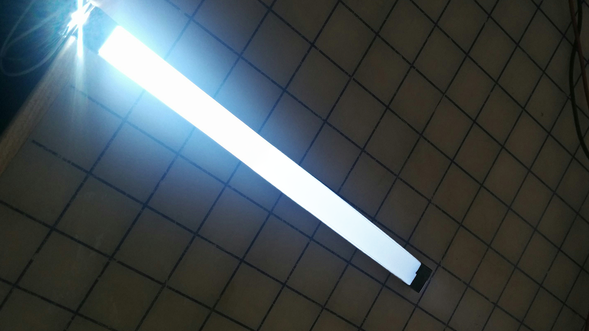
23. We could come back to tweak the blend pattern (reducing the number of dots at the beginning of the light pipe and increasing it toward the end).

Get in touch


